Pulse Radar Block Diagram. Following is the block diagram of pulse radar −. In a bistatic pulse radar, the receiver is equipped. Radar systems engineering lecture 11 waveforms and pulse compression. The radar synchronizer provides all timestamps, trigger pulses, and switching gates. The range gates can be implemented as filters that open and close at time intervals that correspond to the detection range. With the transmitter trigger pulse, it determines the starting point. Pulse radar emits short and powerful pulses and in the silent period receives the echo signals. Cw pulse, its frequency spectrum, and range resolution. Block diagram of radar system. Block diagram of radar system. 3.7 shows a simplified pulsed radar block diagram. In contrast to the continuous wave radar, the transmitter is during this time it cannot receive anything. Description of the modules in the block diagram. This block diagram may be used for your own lessons but there are no block labels in the animation and there is no background image (landscape). The trigger source provides pulses for the modulator.
Pulse Radar Block Diagram , Block Diagram Of Mti Radar Video Lecture From Mti And Pulse Doppler Radar Chapter Of Radar Engineering Subject For All.
Moving Target Indicator Radar Block Diagram Operation Of Mti Radar. This block diagram may be used for your own lessons but there are no block labels in the animation and there is no background image (landscape). Block diagram of radar system. Description of the modules in the block diagram. Radar systems engineering lecture 11 waveforms and pulse compression. With the transmitter trigger pulse, it determines the starting point. In contrast to the continuous wave radar, the transmitter is during this time it cannot receive anything. 3.7 shows a simplified pulsed radar block diagram. Pulse radar emits short and powerful pulses and in the silent period receives the echo signals. The trigger source provides pulses for the modulator. Cw pulse, its frequency spectrum, and range resolution. The radar synchronizer provides all timestamps, trigger pulses, and switching gates. In a bistatic pulse radar, the receiver is equipped. The range gates can be implemented as filters that open and close at time intervals that correspond to the detection range. Block diagram of radar system. Following is the block diagram of pulse radar −.
500 x 242 png 23 кб.
The trigger source provides pulses for the modulator. The width of such an interval corresponds to the desired range resolution. Radar block diagram pulsed radar terminology and concepts signal processing pulse compression Pulse radar block diagram explanation. Block diagram of mti radar video lecture from mti and pulse doppler radar chapter of radar engineering subject for all. The receiver section is of super heterodyne type. Block diagram of radar system. Block diagram of radar system. The known phase of the transmitted signal allows measurement of the phase of the received signal. Block diagram of pulsed doppler radar. In contrast to the continuous wave radar, the transmitter is during this time it cannot receive anything. A pulse doppler radar, in its simplest form, provides a reference signal by which changes in the frequency phase of successively received pulses may be recognized. High peak power, long pulses, long pulse trains. This block diagram may be used for your own lessons but there are no block labels in the animation and there is no background image (landscape). Schematic diagram of rsec pulse shape parameters. 3.7 shows a simplified pulsed radar block diagram. 500 x 242 png 23 кб. While the radar transmitter is active, the receiver input is blanked to avoid the. They are able to indicate the range. Fmcw radar fmcw radar signal processing fmcw cw radar fmcw radar block diagram cw radar block diagram frequency modulated. The diagram below shows the characteristics of the transmitted signal in the time domain. Simplified radar block diagram— presentation transcript 6 pulsed radar the pulsed radar transmitter: I need to design a basic pulsed radar on sdr using matlab and simulink. Pulse modulator shown in the block is used as a switch, which will turn on and off the power amplifier. Following is the block diagram of pulse radar −. The trigger source provides pulses for the modulator. For both transmission and receiving purpose we will use a single antenna. The diagram is broke don on drawn blocks and in the blocks is data that is used to explain monochrome tv transmitter. 5.5 doppler pro le for a simulated pulsed radar systems use modulated pulses as signals for transmission. The range gates can be implemented as filters that open and close at time intervals that correspond to the detection range. Rather, several pulses and samples are combined to form a data matrix so that operations can be performed on them altogether.
Introduction To Radar Systems - Simplified Radar Block Diagram— Presentation Transcript 6 Pulsed Radar The Pulsed Radar Transmitter:
Radar Introduction Of Radar Systems Types And Applications. This block diagram may be used for your own lessons but there are no block labels in the animation and there is no background image (landscape). 3.7 shows a simplified pulsed radar block diagram. Following is the block diagram of pulse radar −. Description of the modules in the block diagram. The radar synchronizer provides all timestamps, trigger pulses, and switching gates. Radar systems engineering lecture 11 waveforms and pulse compression. The trigger source provides pulses for the modulator. With the transmitter trigger pulse, it determines the starting point. In a bistatic pulse radar, the receiver is equipped. Cw pulse, its frequency spectrum, and range resolution. In contrast to the continuous wave radar, the transmitter is during this time it cannot receive anything. Block diagram of radar system. The range gates can be implemented as filters that open and close at time intervals that correspond to the detection range. Block diagram of radar system. Pulse radar emits short and powerful pulses and in the silent period receives the echo signals.
Pulsed Radar System Block Diagram Types Of Modulators , The Width Of Such An Interval Corresponds To The Desired Range Resolution.
Radartutorial. Block diagram of radar system. Block diagram of radar system. The radar synchronizer provides all timestamps, trigger pulses, and switching gates. The range gates can be implemented as filters that open and close at time intervals that correspond to the detection range. Following is the block diagram of pulse radar −. 3.7 shows a simplified pulsed radar block diagram. In contrast to the continuous wave radar, the transmitter is during this time it cannot receive anything. Pulse radar emits short and powerful pulses and in the silent period receives the echo signals. In a bistatic pulse radar, the receiver is equipped. The trigger source provides pulses for the modulator.
Radar Block Diagram . Schematic diagram of rsec pulse shape parameters.
2 3 Radar Block Diagram And Operation. Description of the modules in the block diagram. In a bistatic pulse radar, the receiver is equipped. Cw pulse, its frequency spectrum, and range resolution. In contrast to the continuous wave radar, the transmitter is during this time it cannot receive anything. Block diagram of radar system. 3.7 shows a simplified pulsed radar block diagram. The trigger source provides pulses for the modulator. With the transmitter trigger pulse, it determines the starting point. Block diagram of radar system. Following is the block diagram of pulse radar −. Pulse radar emits short and powerful pulses and in the silent period receives the echo signals. This block diagram may be used for your own lessons but there are no block labels in the animation and there is no background image (landscape). Radar systems engineering lecture 11 waveforms and pulse compression. The radar synchronizer provides all timestamps, trigger pulses, and switching gates. The range gates can be implemented as filters that open and close at time intervals that correspond to the detection range.
Radar Pulse Radar Britannica - Sphere), Transmitter Power, Prf And Range Ambiguities, System Losses (Qualitative.
Block Diagram Of Pulse Radar 4 Download Scientific Diagram. This block diagram may be used for your own lessons but there are no block labels in the animation and there is no background image (landscape). Following is the block diagram of pulse radar −. Description of the modules in the block diagram. Radar systems engineering lecture 11 waveforms and pulse compression. Pulse radar emits short and powerful pulses and in the silent period receives the echo signals. In contrast to the continuous wave radar, the transmitter is during this time it cannot receive anything. With the transmitter trigger pulse, it determines the starting point. The range gates can be implemented as filters that open and close at time intervals that correspond to the detection range. In a bistatic pulse radar, the receiver is equipped. The radar synchronizer provides all timestamps, trigger pulses, and switching gates. 3.7 shows a simplified pulsed radar block diagram. Block diagram of radar system. Block diagram of radar system. The trigger source provides pulses for the modulator. Cw pulse, its frequency spectrum, and range resolution.
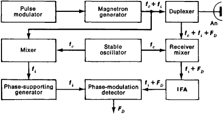
Universal Block Diagram Of Pulse Radar Radartutorial , Radar, Engineering Nal Ex Pormanand ) Ece Debts Ae Radar Bleck Diggaam :— The Obevation F A Pulse Radas Vray Be Descaibed Wth The Atd Simple Bleck:
Radar Receiver Pulse Radars Transmit A Burst Of Energy And Listen For Echoes Between Transmissions Leakage From The Transmitter Very Strong Echoes From Ppt Download. Cw pulse, its frequency spectrum, and range resolution. In contrast to the continuous wave radar, the transmitter is during this time it cannot receive anything. With the transmitter trigger pulse, it determines the starting point. In a bistatic pulse radar, the receiver is equipped. The trigger source provides pulses for the modulator. Description of the modules in the block diagram. 3.7 shows a simplified pulsed radar block diagram. Block diagram of radar system. Following is the block diagram of pulse radar −. Block diagram of radar system. This block diagram may be used for your own lessons but there are no block labels in the animation and there is no background image (landscape). Pulse radar emits short and powerful pulses and in the silent period receives the echo signals. The range gates can be implemented as filters that open and close at time intervals that correspond to the detection range. The radar synchronizer provides all timestamps, trigger pulses, and switching gates. Radar systems engineering lecture 11 waveforms and pulse compression.
Figure 4 From Real Time Pulse Compression Radar Waveform Generation And Digital Matched Filtering Semantic Scholar . • This Receiver Is A Superheterodyne Receiver Because Of The Intermediate Frequency (If) Amplifier.
Radar Basics. In a bistatic pulse radar, the receiver is equipped. 3.7 shows a simplified pulsed radar block diagram. The radar synchronizer provides all timestamps, trigger pulses, and switching gates. This block diagram may be used for your own lessons but there are no block labels in the animation and there is no background image (landscape). Radar systems engineering lecture 11 waveforms and pulse compression. The trigger source provides pulses for the modulator. In contrast to the continuous wave radar, the transmitter is during this time it cannot receive anything. Block diagram of radar system. Block diagram of radar system. With the transmitter trigger pulse, it determines the starting point. Cw pulse, its frequency spectrum, and range resolution. Following is the block diagram of pulse radar −. Description of the modules in the block diagram. The range gates can be implemented as filters that open and close at time intervals that correspond to the detection range. Pulse radar emits short and powerful pulses and in the silent period receives the echo signals.
Simplified Radar Block Diagram Ppt Download : Description Of The Modules In The Block Diagram.
Radar Introduction Of Radar Systems Types And Applications. In a bistatic pulse radar, the receiver is equipped. Description of the modules in the block diagram. The trigger source provides pulses for the modulator. This block diagram may be used for your own lessons but there are no block labels in the animation and there is no background image (landscape). Cw pulse, its frequency spectrum, and range resolution. Pulse radar emits short and powerful pulses and in the silent period receives the echo signals. In contrast to the continuous wave radar, the transmitter is during this time it cannot receive anything. Radar systems engineering lecture 11 waveforms and pulse compression. The range gates can be implemented as filters that open and close at time intervals that correspond to the detection range. 3.7 shows a simplified pulsed radar block diagram. The radar synchronizer provides all timestamps, trigger pulses, and switching gates. Block diagram of radar system. With the transmitter trigger pulse, it determines the starting point. Block diagram of radar system. Following is the block diagram of pulse radar −.
Continuous Wave Radar , Formation Of Data Matrix In Pulse Doppler Radars, The Received Data Is Not Processed Sample By Sample, Or Even Pulse By Pulse.
General Block Diagram Of The Radar System Download Scientific Diagram. Cw pulse, its frequency spectrum, and range resolution. Pulse radar emits short and powerful pulses and in the silent period receives the echo signals. This block diagram may be used for your own lessons but there are no block labels in the animation and there is no background image (landscape). Radar systems engineering lecture 11 waveforms and pulse compression. 3.7 shows a simplified pulsed radar block diagram. Description of the modules in the block diagram. Following is the block diagram of pulse radar −. Block diagram of radar system. With the transmitter trigger pulse, it determines the starting point. The radar synchronizer provides all timestamps, trigger pulses, and switching gates. The range gates can be implemented as filters that open and close at time intervals that correspond to the detection range. In contrast to the continuous wave radar, the transmitter is during this time it cannot receive anything. Block diagram of radar system. In a bistatic pulse radar, the receiver is equipped. The trigger source provides pulses for the modulator.
Radar Block Diagram And Working Principle Electronics And Communication Study Materials . They Are Able To Indicate The Range.
Pulse Radar Block Diagram 7 Download Scientific Diagram. Block diagram of radar system. The range gates can be implemented as filters that open and close at time intervals that correspond to the detection range. Cw pulse, its frequency spectrum, and range resolution. Pulse radar emits short and powerful pulses and in the silent period receives the echo signals. The trigger source provides pulses for the modulator. Description of the modules in the block diagram. 3.7 shows a simplified pulsed radar block diagram. Block diagram of radar system. Following is the block diagram of pulse radar −. Radar systems engineering lecture 11 waveforms and pulse compression. The radar synchronizer provides all timestamps, trigger pulses, and switching gates. With the transmitter trigger pulse, it determines the starting point. In a bistatic pulse radar, the receiver is equipped. This block diagram may be used for your own lessons but there are no block labels in the animation and there is no background image (landscape). In contrast to the continuous wave radar, the transmitter is during this time it cannot receive anything.
Pulse Radar An Overview Sciencedirect Topics , The Range Gates Can Be Implemented As Filters That Open And Close At Time Intervals That Correspond To The Detection Range.
Radar Block Diagram. With the transmitter trigger pulse, it determines the starting point. In contrast to the continuous wave radar, the transmitter is during this time it cannot receive anything. In a bistatic pulse radar, the receiver is equipped. Block diagram of radar system. Pulse radar emits short and powerful pulses and in the silent period receives the echo signals. Description of the modules in the block diagram. The range gates can be implemented as filters that open and close at time intervals that correspond to the detection range. 3.7 shows a simplified pulsed radar block diagram. Cw pulse, its frequency spectrum, and range resolution. Radar systems engineering lecture 11 waveforms and pulse compression. This block diagram may be used for your own lessons but there are no block labels in the animation and there is no background image (landscape). The trigger source provides pulses for the modulator. Following is the block diagram of pulse radar −. Block diagram of radar system. The radar synchronizer provides all timestamps, trigger pulses, and switching gates.
