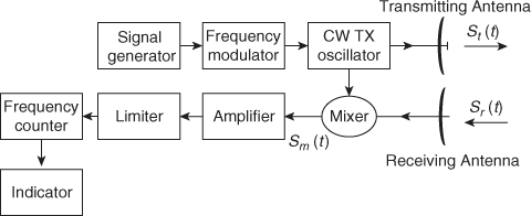
Fmcw Radar Block Diagram. The following figure shows the block diagram of fmcw radar −. Ti mmwave radars are frequency modulated continuous wave (fmcw) radars such that the frequency is swept linearly. The output of the down mixer (see block diagram), a dc voltage. Time characteristic follows the sawtooth pattern shown in figure 1 on the following page. Fmcw radar is mostly used as radar altimeter in order to measure the exact height while landing the aircraft. Figure 1 the frequency modulated continuous wave (fmcw) radar system block diagram is shown. This chirp is then radiated with the antenna, reflected from the target and is received by the receiving antenna. 1 in which both the transmitter and the receiver are at the same location. Fmcw radar contains two antennas − transmitting antenna and receiving antenna as shown in the figure. The chirp then travels down to the target and gets reflected back. Basically an fmcw radar is a continuous wave radar that transmits frequency sweeps called chirps . Frequency modulated continuous wave (fmcw) radar works by transmitting a chirp which frequency changes linearly with time. The transmitter generates the fmcw waveform and the same waveform is used for the demodulation of the signal from the receiver antenna. A simplied block diagram of such a system is shown in fig. You will explore fmcw radar systems with both sawtooth and triangular chirp modulations and see how the target range and velocity information are extracted from the output beat signals.
Fmcw Radar Block Diagram : The Program Fmcw_Sim.grc Is A Simulation Of Fmcw Radar, As Simple As Possible.
Radar Systems Mti Radar Tutorialspoint. The following figure shows the block diagram of fmcw radar −. This chirp is then radiated with the antenna, reflected from the target and is received by the receiving antenna. You will explore fmcw radar systems with both sawtooth and triangular chirp modulations and see how the target range and velocity information are extracted from the output beat signals. 1 in which both the transmitter and the receiver are at the same location. Time characteristic follows the sawtooth pattern shown in figure 1 on the following page. Fmcw radar contains two antennas − transmitting antenna and receiving antenna as shown in the figure. The chirp then travels down to the target and gets reflected back. Basically an fmcw radar is a continuous wave radar that transmits frequency sweeps called chirps . Frequency modulated continuous wave (fmcw) radar works by transmitting a chirp which frequency changes linearly with time. Ti mmwave radars are frequency modulated continuous wave (fmcw) radars such that the frequency is swept linearly. Figure 1 the frequency modulated continuous wave (fmcw) radar system block diagram is shown. Fmcw radar is mostly used as radar altimeter in order to measure the exact height while landing the aircraft. A simplied block diagram of such a system is shown in fig. The output of the down mixer (see block diagram), a dc voltage. The transmitter generates the fmcw waveform and the same waveform is used for the demodulation of the signal from the receiver antenna.
The frequency modulated continuous wave (fmcw) technique (barriok 1973 ;
Figure 1 the frequency modulated continuous wave (fmcw) radar system block diagram is shown. Ti mmwave radars are frequency modulated continuous wave (fmcw) radars such that the frequency is swept linearly. Radar cross section (rcs) analysis allowing for an understanding of the varying detectability of objects based on material, absolute and relative size, reflection angle, distance and strength of the signal. Figure 5 shows a block diagram of the linear fm frequency synthesizer, where the constituent components and interconnections have been identified. One is the structure with separate transmitting and. Velocity information is extracted by doppler effect caused by motion between target and the radar. The range resolution is a critical concept (2.5). The transmitter generates the fmcw waveform and the same waveform is used for the demodulation of the signal from the receiver antenna. More detailed coverage of this topic will be presented in chapter 2. Individual objects are detected using the doppler effect. Single antenna fmcw radar architecture the block diagram in figure 1 illustrates the typical architecture of a single. 1.limitation of cw radar 2.fmcw radar 3.frequency modulated continuous wave radar 4.fmcw radar system 5.fmcw doppler radar 6.ranging with an fmcw radar 7.features of fmcw radar 8.block diagram of. Block diagram of an fmcw radar for precipitation measurements delft university of technology remote sensing of the environment. You will explore fmcw radar systems with both sawtooth and triangular chirp modulations and see how the target range and velocity information are extracted from the output beat signals. 1 shows the block diagram of fmcw radar system. Fmcw radar is a better candidate for applications that require range information, such as localization, fall detection, life activity monitoring and gesture. Frequency modulated continuous wave (fmcw) radar uses a modulated cw to sense both the range and doppler properties of targets. It leaves the receive signal glitches inherent to the resetting of the sawtooth and triangle waveforms. N why fmcw for concealed weapon detection. The program fmcw_sim.grc is a simulation of fmcw radar, as simple as possible. Basically an fmcw radar is a continuous wave radar that transmits frequency sweeps called chirps . The frequency modulated continuous wave (fmcw) technique (barriok 1973 ; A simplied block diagram of such a system is shown in fig. The chirp generator acts as the signal source at the transmitter and mixer input of receiver too. We can use two basic block diagrams to illustrate the principle of the fmcw radar. I started off by making a block diagram of my design. Time characteristic follows the sawtooth pattern shown in figure 1 on the following page. Frequency modulated continuous wave (fmcw) radar has wide application areas in both civil and military use. It can be used to sdtetct un stationary targets as distance measurement cannot be performed. E • …frequency modulated continuous wave (fmcw). Fmcw radar design by m.
Block Diagram Of The 24ghz Fmcw Radar System Download Scientific Diagram : The Frequency Modulated Continuous Wave (Fmcw) Technique (Barriok 1973 ;
Continuous Wave Radar Wikipedia. This chirp is then radiated with the antenna, reflected from the target and is received by the receiving antenna. Fmcw radar is mostly used as radar altimeter in order to measure the exact height while landing the aircraft. The output of the down mixer (see block diagram), a dc voltage. Ti mmwave radars are frequency modulated continuous wave (fmcw) radars such that the frequency is swept linearly. You will explore fmcw radar systems with both sawtooth and triangular chirp modulations and see how the target range and velocity information are extracted from the output beat signals. The transmitter generates the fmcw waveform and the same waveform is used for the demodulation of the signal from the receiver antenna. Fmcw radar contains two antennas − transmitting antenna and receiving antenna as shown in the figure. Time characteristic follows the sawtooth pattern shown in figure 1 on the following page. Basically an fmcw radar is a continuous wave radar that transmits frequency sweeps called chirps . The chirp then travels down to the target and gets reflected back. Figure 1 the frequency modulated continuous wave (fmcw) radar system block diagram is shown. 1 in which both the transmitter and the receiver are at the same location. A simplied block diagram of such a system is shown in fig. Frequency modulated continuous wave (fmcw) radar works by transmitting a chirp which frequency changes linearly with time. The following figure shows the block diagram of fmcw radar −.
Radar Systems Fmcw Radar Tutorialspoint - The Following Figure Shows The Block Diagram Of Fmcw Radar −.
Fmcw Radar Electronics Club Radar Engineering Fmcw Radar Electronics Club. The transmitter generates the fmcw waveform and the same waveform is used for the demodulation of the signal from the receiver antenna. Ti mmwave radars are frequency modulated continuous wave (fmcw) radars such that the frequency is swept linearly. This chirp is then radiated with the antenna, reflected from the target and is received by the receiving antenna. A simplied block diagram of such a system is shown in fig. Fmcw radar is mostly used as radar altimeter in order to measure the exact height while landing the aircraft. You will explore fmcw radar systems with both sawtooth and triangular chirp modulations and see how the target range and velocity information are extracted from the output beat signals. The following figure shows the block diagram of fmcw radar −. Basically an fmcw radar is a continuous wave radar that transmits frequency sweeps called chirps . Frequency modulated continuous wave (fmcw) radar works by transmitting a chirp which frequency changes linearly with time. The output of the down mixer (see block diagram), a dc voltage.
Fmcw Radar Us 10 444 326 B2 Patentswarm . Fmcw radar is a better candidate for applications that require range information, such as localization, fall detection, life activity monitoring and gesture.
Design Of An Fmcw Radar Baseband Signal Processing System For Automotive Application Springerplus Full Text. Basically an fmcw radar is a continuous wave radar that transmits frequency sweeps called chirps . A simplied block diagram of such a system is shown in fig. Fmcw radar is mostly used as radar altimeter in order to measure the exact height while landing the aircraft. Fmcw radar contains two antennas − transmitting antenna and receiving antenna as shown in the figure. This chirp is then radiated with the antenna, reflected from the target and is received by the receiving antenna. The output of the down mixer (see block diagram), a dc voltage. Time characteristic follows the sawtooth pattern shown in figure 1 on the following page. You will explore fmcw radar systems with both sawtooth and triangular chirp modulations and see how the target range and velocity information are extracted from the output beat signals. The chirp then travels down to the target and gets reflected back. Frequency modulated continuous wave (fmcw) radar works by transmitting a chirp which frequency changes linearly with time. 1 in which both the transmitter and the receiver are at the same location. Ti mmwave radars are frequency modulated continuous wave (fmcw) radars such that the frequency is swept linearly. The following figure shows the block diagram of fmcw radar −. The transmitter generates the fmcw waveform and the same waveform is used for the demodulation of the signal from the receiver antenna. Figure 1 the frequency modulated continuous wave (fmcw) radar system block diagram is shown.
Development Of A Low Cost Short Range Radar System To Measure Speed And Distance . Block Diagram Of An Fmcw Radar For Precipitation Measurements Delft University Of Technology Remote Sensing Of The Environment.
Third Version Of Homemade 6 Ghz Fmcw Radar Henrik S Blog. 1 in which both the transmitter and the receiver are at the same location. Fmcw radar is mostly used as radar altimeter in order to measure the exact height while landing the aircraft. Figure 1 the frequency modulated continuous wave (fmcw) radar system block diagram is shown. The following figure shows the block diagram of fmcw radar −. The chirp then travels down to the target and gets reflected back. The output of the down mixer (see block diagram), a dc voltage. The transmitter generates the fmcw waveform and the same waveform is used for the demodulation of the signal from the receiver antenna. Ti mmwave radars are frequency modulated continuous wave (fmcw) radars such that the frequency is swept linearly. A simplied block diagram of such a system is shown in fig. Basically an fmcw radar is a continuous wave radar that transmits frequency sweeps called chirps . This chirp is then radiated with the antenna, reflected from the target and is received by the receiving antenna. Fmcw radar contains two antennas − transmitting antenna and receiving antenna as shown in the figure. You will explore fmcw radar systems with both sawtooth and triangular chirp modulations and see how the target range and velocity information are extracted from the output beat signals. Time characteristic follows the sawtooth pattern shown in figure 1 on the following page. Frequency modulated continuous wave (fmcw) radar works by transmitting a chirp which frequency changes linearly with time.
Block Diagram Of Ds Fmcw Radar System Download Scientific Diagram - It Leaves The Receive Signal Glitches Inherent To The Resetting Of The Sawtooth And Triangle Waveforms.
Fmcw Radar Analysis And Signal Simulation Youtube. The transmitter generates the fmcw waveform and the same waveform is used for the demodulation of the signal from the receiver antenna. The chirp then travels down to the target and gets reflected back. 1 in which both the transmitter and the receiver are at the same location. Time characteristic follows the sawtooth pattern shown in figure 1 on the following page. The following figure shows the block diagram of fmcw radar −. The output of the down mixer (see block diagram), a dc voltage. Basically an fmcw radar is a continuous wave radar that transmits frequency sweeps called chirps . This chirp is then radiated with the antenna, reflected from the target and is received by the receiving antenna. You will explore fmcw radar systems with both sawtooth and triangular chirp modulations and see how the target range and velocity information are extracted from the output beat signals. Fmcw radar contains two antennas − transmitting antenna and receiving antenna as shown in the figure. A simplied block diagram of such a system is shown in fig. Fmcw radar is mostly used as radar altimeter in order to measure the exact height while landing the aircraft. Figure 1 the frequency modulated continuous wave (fmcw) radar system block diagram is shown. Ti mmwave radars are frequency modulated continuous wave (fmcw) radars such that the frequency is swept linearly. Frequency modulated continuous wave (fmcw) radar works by transmitting a chirp which frequency changes linearly with time.
Block Diagram Of Ds Fmcw Radar System Download Scientific Diagram . We Can Use Two Basic Block Diagrams To Illustrate The Principle Of The Fmcw Radar.
Automotive Adaptive Cruise Control Using Fmcw And Mfsk Technology Matlab Simulink. Ti mmwave radars are frequency modulated continuous wave (fmcw) radars such that the frequency is swept linearly. A simplied block diagram of such a system is shown in fig. Time characteristic follows the sawtooth pattern shown in figure 1 on the following page. The chirp then travels down to the target and gets reflected back. You will explore fmcw radar systems with both sawtooth and triangular chirp modulations and see how the target range and velocity information are extracted from the output beat signals. This chirp is then radiated with the antenna, reflected from the target and is received by the receiving antenna. The transmitter generates the fmcw waveform and the same waveform is used for the demodulation of the signal from the receiver antenna. 1 in which both the transmitter and the receiver are at the same location. Figure 1 the frequency modulated continuous wave (fmcw) radar system block diagram is shown. The following figure shows the block diagram of fmcw radar −. The output of the down mixer (see block diagram), a dc voltage. Basically an fmcw radar is a continuous wave radar that transmits frequency sweeps called chirps . Fmcw radar contains two antennas − transmitting antenna and receiving antenna as shown in the figure. Fmcw radar is mostly used as radar altimeter in order to measure the exact height while landing the aircraft. Frequency modulated continuous wave (fmcw) radar works by transmitting a chirp which frequency changes linearly with time.
Basics Of Fmcw Radar Radar Operation Part 2 Pasternack Blog . Frequency Modulated Continuous Wave (Fmcw) Radar Works By Transmitting A Chirp Which Frequency Changes Linearly With Time.
Explain Cw Doppler Radar. The transmitter generates the fmcw waveform and the same waveform is used for the demodulation of the signal from the receiver antenna. You will explore fmcw radar systems with both sawtooth and triangular chirp modulations and see how the target range and velocity information are extracted from the output beat signals. The chirp then travels down to the target and gets reflected back. Figure 1 the frequency modulated continuous wave (fmcw) radar system block diagram is shown. A simplied block diagram of such a system is shown in fig. Basically an fmcw radar is a continuous wave radar that transmits frequency sweeps called chirps . This chirp is then radiated with the antenna, reflected from the target and is received by the receiving antenna. 1 in which both the transmitter and the receiver are at the same location. Fmcw radar contains two antennas − transmitting antenna and receiving antenna as shown in the figure. Ti mmwave radars are frequency modulated continuous wave (fmcw) radars such that the frequency is swept linearly. Frequency modulated continuous wave (fmcw) radar works by transmitting a chirp which frequency changes linearly with time. The following figure shows the block diagram of fmcw radar −. Fmcw radar is mostly used as radar altimeter in order to measure the exact height while landing the aircraft. Time characteristic follows the sawtooth pattern shown in figure 1 on the following page. The output of the down mixer (see block diagram), a dc voltage.
Fmcw Radar Block Diagram Nuclearrambo - The Chirp Then Travels Down To The Target And Gets Reflected Back.
Advanced Solutions Nederland Example Fmcw Radar Model. The output of the down mixer (see block diagram), a dc voltage. A simplied block diagram of such a system is shown in fig. Basically an fmcw radar is a continuous wave radar that transmits frequency sweeps called chirps . The transmitter generates the fmcw waveform and the same waveform is used for the demodulation of the signal from the receiver antenna. Fmcw radar contains two antennas − transmitting antenna and receiving antenna as shown in the figure. You will explore fmcw radar systems with both sawtooth and triangular chirp modulations and see how the target range and velocity information are extracted from the output beat signals. 1 in which both the transmitter and the receiver are at the same location. Figure 1 the frequency modulated continuous wave (fmcw) radar system block diagram is shown. The chirp then travels down to the target and gets reflected back. Frequency modulated continuous wave (fmcw) radar works by transmitting a chirp which frequency changes linearly with time. The following figure shows the block diagram of fmcw radar −. This chirp is then radiated with the antenna, reflected from the target and is received by the receiving antenna. Fmcw radar is mostly used as radar altimeter in order to measure the exact height while landing the aircraft. Time characteristic follows the sawtooth pattern shown in figure 1 on the following page. Ti mmwave radars are frequency modulated continuous wave (fmcw) radars such that the frequency is swept linearly.
Frequency Modulated Continuous Wave Fmcw Radar Wolfram Demonstrations Project - The Range Resolution Is A Critical Concept (2.5).
Fmcw Radar Us 10 444 326 B2 Patentswarm. A simplied block diagram of such a system is shown in fig. Basically an fmcw radar is a continuous wave radar that transmits frequency sweeps called chirps . The following figure shows the block diagram of fmcw radar −. 1 in which both the transmitter and the receiver are at the same location. The output of the down mixer (see block diagram), a dc voltage. Frequency modulated continuous wave (fmcw) radar works by transmitting a chirp which frequency changes linearly with time. Fmcw radar contains two antennas − transmitting antenna and receiving antenna as shown in the figure. You will explore fmcw radar systems with both sawtooth and triangular chirp modulations and see how the target range and velocity information are extracted from the output beat signals. Ti mmwave radars are frequency modulated continuous wave (fmcw) radars such that the frequency is swept linearly. Fmcw radar is mostly used as radar altimeter in order to measure the exact height while landing the aircraft. The chirp then travels down to the target and gets reflected back. The transmitter generates the fmcw waveform and the same waveform is used for the demodulation of the signal from the receiver antenna. Time characteristic follows the sawtooth pattern shown in figure 1 on the following page. Figure 1 the frequency modulated continuous wave (fmcw) radar system block diagram is shown. This chirp is then radiated with the antenna, reflected from the target and is received by the receiving antenna.
The Radar Technology Behind Autonomous Vehicles Electrical Engineering News And Products . The Chirp Generator Acts As The Signal Source At The Transmitter And Mixer Input Of Receiver Too.
Frequency Modulated Continuous Wave Radar Block Diagram Electronics And Communication Study Materials. Ti mmwave radars are frequency modulated continuous wave (fmcw) radars such that the frequency is swept linearly. Frequency modulated continuous wave (fmcw) radar works by transmitting a chirp which frequency changes linearly with time. Basically an fmcw radar is a continuous wave radar that transmits frequency sweeps called chirps . This chirp is then radiated with the antenna, reflected from the target and is received by the receiving antenna. A simplied block diagram of such a system is shown in fig. You will explore fmcw radar systems with both sawtooth and triangular chirp modulations and see how the target range and velocity information are extracted from the output beat signals. The following figure shows the block diagram of fmcw radar −. Fmcw radar is mostly used as radar altimeter in order to measure the exact height while landing the aircraft. The transmitter generates the fmcw waveform and the same waveform is used for the demodulation of the signal from the receiver antenna. Figure 1 the frequency modulated continuous wave (fmcw) radar system block diagram is shown. The chirp then travels down to the target and gets reflected back. Time characteristic follows the sawtooth pattern shown in figure 1 on the following page. 1 in which both the transmitter and the receiver are at the same location. The output of the down mixer (see block diagram), a dc voltage. Fmcw radar contains two antennas − transmitting antenna and receiving antenna as shown in the figure.
