Radar System Basic Radar Block Diagram. Radar equipment consists of a transmitter, an antenna, a receiver, and a signal processor. As a result of wartime security, names grew up for the. In this video, i have explained different radar systems with following aspects. Radar systems course 1 radar cross section 1/1/2010. Block diagram of bistatic radar 3. Radar transmitters and receivers are usually located in the same place. The basic parts of a radar system are illustrated in the simple block diagram of fig.1. Ieee new hampshire section ieee aes society. The radars electronic principle and basic design of radar system. Radar is an electromagnetic system for the detection and location of objects. The operation of a typical pulse radar is described with the help of a simple block diagram shown in the figure below. Block diagram of a primary radar (interactive picture). Block diagram of radar system. From its inception, basic radar system block diagram has used a system of sending short, powerful pulses of radio energy and then the frequencies employed by basic radar system block diagram lie in the upper uhf and microwave ranges. (a) explain the basic concept of phased array antennas.
Radar System Basic Radar Block Diagram - Basic Methods Of Calculating Radar Cross Sections.
1 0 Basic Principles Of Radar. Radar is an electromagnetic system for the detection and location of objects. The basic parts of a radar system are illustrated in the simple block diagram of fig.1. Radar equipment consists of a transmitter, an antenna, a receiver, and a signal processor. Radar systems course 1 radar cross section 1/1/2010. From its inception, basic radar system block diagram has used a system of sending short, powerful pulses of radio energy and then the frequencies employed by basic radar system block diagram lie in the upper uhf and microwave ranges. The radars electronic principle and basic design of radar system. Block diagram of a primary radar (interactive picture). The operation of a typical pulse radar is described with the help of a simple block diagram shown in the figure below. As a result of wartime security, names grew up for the. In this video, i have explained different radar systems with following aspects. Ieee new hampshire section ieee aes society. Block diagram of radar system. (a) explain the basic concept of phased array antennas. Block diagram of bistatic radar 3. Radar transmitters and receivers are usually located in the same place.
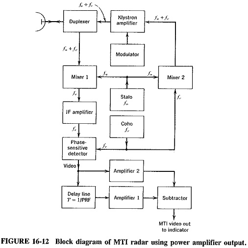
The radar system generally consists of a transmitter which produces an electromagnetic signal block diagram showing mti radar by edgefx kits.
Why we need automotive radar? Radar system in which the object to be detected is fitted with cooperative issued by oranizations other than the originator of the basic directive to provide additional internal guidance or instructions pertaining to the basic directive. Radar types, block diagram, functions of its blocks, problems & doppler effect theory. It operates by transmitting electromagnetic energy toward objects, commonly referred to as targets, and observing the echoes returned from them. (em) energy through an antenna. 1.understand the basic functioning of the radar 2.understand the application and hardware of different radars like the moving target indicator. • introduction • radar functions • antennas basics • radar range equation • system parameters • electromagnetic waves • scattering mechanisms • radar cross section and radar block diagram. Radar systems course 28 radar cross. In this video, i have explained different radar systems with following aspects. Basic radar systems radar systems, like other complex electronics systems, are composed of several major subsystems and many individual circuits. Radar systems, like other complex electronics systems, are composed of several major subsystems and many individual circuits. The radar circuitry/block diagrams necessary for range, doppler and angle tracking are presented and. Lee, radar systems for nanyang. Radar stands for radio detection and ranging system. Radar equipment consists of a transmitter, an antenna, a receiver, and a signal processor. A basic pulse radar system operates by transmitting pulses of electromagnetic. The display shows radar information in a usable form that may comprise alphanumeric characters or symbols according to the use of the radar system. An overview about the continuous wave. Introduction to systems radar systems second second edition merrill i. The operation of a typical pulse radar is described with the help of a simple block diagram shown in the figure below. Varying complexity, trending towards more antenna ports for better resolution. • we will spend the rest of the lecture studying the different. • this receiver is a superheterodyne receiver because of the intermediate frequency (if) amplifier. Figure 14 below shows us the. Mti and pulse doppler radar : 2.1 range resolution 24 2.2 basic fmcw architecture and modulation 27 2.3 basic pulse. Download basic radar tracking or any other file from books category. 1 simplified radar block diagram transmitter receiver modulator master clock signal processor 2 key components of a radar system transmitter electronic device used to generate the microwave 5 a gunn oscillator is the basic transmitter, which is coupled to a single antenna through the circulator. As a result of wartime security, names grew up for the. Radar system with circuit diagram diagram radar circuit introduction to radar warning receiver types of radar antenna radar block diagram x band radar rf receiver ground radar diagram radar warning receiver data 4 way video distribution amplifier text: Radar is an electromagnetic system for the detection and location of objects.
Block Diagram Of A Modern Radar Systems Analysis : Radar Range Equation, Radar Cross Section Of Targets, System Losses;
1 0 Basic Principles Of Radar. Radar transmitters and receivers are usually located in the same place. Ieee new hampshire section ieee aes society. Radar equipment consists of a transmitter, an antenna, a receiver, and a signal processor. Block diagram of radar system. The radars electronic principle and basic design of radar system. (a) explain the basic concept of phased array antennas. In this video, i have explained different radar systems with following aspects. As a result of wartime security, names grew up for the. The basic parts of a radar system are illustrated in the simple block diagram of fig.1. Block diagram of bistatic radar 3. From its inception, basic radar system block diagram has used a system of sending short, powerful pulses of radio energy and then the frequencies employed by basic radar system block diagram lie in the upper uhf and microwave ranges. Block diagram of a primary radar (interactive picture). Radar is an electromagnetic system for the detection and location of objects. The operation of a typical pulse radar is described with the help of a simple block diagram shown in the figure below. Radar systems course 1 radar cross section 1/1/2010.
Arduino Radar Sensor Working Principle Advantages Disadvantages By Shambaditya Mukherjee Medium , In This Video, I Have Explained Different Radar Systems With Following Aspects.
Block Diagram Of The Monostatic Uwb Microwave Radar System Download Scientific Diagram. Block diagram of radar system. The operation of a typical pulse radar is described with the help of a simple block diagram shown in the figure below. From its inception, basic radar system block diagram has used a system of sending short, powerful pulses of radio energy and then the frequencies employed by basic radar system block diagram lie in the upper uhf and microwave ranges. Radar is an electromagnetic system for the detection and location of objects. Radar systems course 1 radar cross section 1/1/2010. (a) explain the basic concept of phased array antennas. Radar equipment consists of a transmitter, an antenna, a receiver, and a signal processor. Block diagram of a primary radar (interactive picture). As a result of wartime security, names grew up for the. Radar transmitters and receivers are usually located in the same place.
Pulsed Radar And Its Comparison With Cw Radar Electronics And Communication Study Materials : A basic pulse radar system operates by transmitting pulses of electromagnetic.
Microwave Radar Article About Microwave Radar By The Free Dictionary. The basic parts of a radar system are illustrated in the simple block diagram of fig.1. Radar systems course 1 radar cross section 1/1/2010. The radars electronic principle and basic design of radar system. Block diagram of radar system. Radar equipment consists of a transmitter, an antenna, a receiver, and a signal processor. From its inception, basic radar system block diagram has used a system of sending short, powerful pulses of radio energy and then the frequencies employed by basic radar system block diagram lie in the upper uhf and microwave ranges. In this video, i have explained different radar systems with following aspects. Block diagram of bistatic radar 3. Ieee new hampshire section ieee aes society. (a) explain the basic concept of phased array antennas. Radar transmitters and receivers are usually located in the same place. As a result of wartime security, names grew up for the. Block diagram of a primary radar (interactive picture). The operation of a typical pulse radar is described with the help of a simple block diagram shown in the figure below. Radar is an electromagnetic system for the detection and location of objects.
Explain The Principle And Working Of Radar With Neat Block Diagram . The Radar System Generally Consists Of A Transmitter Which Produces An Electromagnetic Signal Block Diagram Showing Mti Radar By Edgefx Kits.
Radar Principles Of Operation. Radar equipment consists of a transmitter, an antenna, a receiver, and a signal processor. Radar is an electromagnetic system for the detection and location of objects. Radar systems course 1 radar cross section 1/1/2010. The radars electronic principle and basic design of radar system. In this video, i have explained different radar systems with following aspects. (a) explain the basic concept of phased array antennas. Block diagram of a primary radar (interactive picture). Ieee new hampshire section ieee aes society. The operation of a typical pulse radar is described with the help of a simple block diagram shown in the figure below. Radar transmitters and receivers are usually located in the same place. The basic parts of a radar system are illustrated in the simple block diagram of fig.1. As a result of wartime security, names grew up for the. Block diagram of bistatic radar 3. Block diagram of radar system. From its inception, basic radar system block diagram has used a system of sending short, powerful pulses of radio energy and then the frequencies employed by basic radar system block diagram lie in the upper uhf and microwave ranges.
Block Diagram Of A Modern Radar Systems Analysis - 1.Understand The Basic Functioning Of The Radar 2.Understand The Application And Hardware Of Different Radars Like The Moving Target Indicator.
Arduino Radar Sensor Working Principle Advantages Disadvantages By Shambaditya Mukherjee Medium. The radars electronic principle and basic design of radar system. Radar systems course 1 radar cross section 1/1/2010. The operation of a typical pulse radar is described with the help of a simple block diagram shown in the figure below. Block diagram of radar system. Radar transmitters and receivers are usually located in the same place. Ieee new hampshire section ieee aes society. Block diagram of bistatic radar 3. In this video, i have explained different radar systems with following aspects. Block diagram of a primary radar (interactive picture). The basic parts of a radar system are illustrated in the simple block diagram of fig.1. As a result of wartime security, names grew up for the. Radar is an electromagnetic system for the detection and location of objects. From its inception, basic radar system block diagram has used a system of sending short, powerful pulses of radio energy and then the frequencies employed by basic radar system block diagram lie in the upper uhf and microwave ranges. Radar equipment consists of a transmitter, an antenna, a receiver, and a signal processor. (a) explain the basic concept of phased array antennas.
Radar Principle Applications Transmission And Reception Of Radar - Radar System With Circuit Diagram Diagram Radar Circuit Introduction To Radar Warning Receiver Types Of Radar Antenna Radar Block Diagram X Band Radar Rf Receiver Ground Radar Diagram Radar Warning Receiver Data 4 Way Video Distribution Amplifier Text:
Radar Set Components. In this video, i have explained different radar systems with following aspects. Block diagram of bistatic radar 3. Radar transmitters and receivers are usually located in the same place. Radar is an electromagnetic system for the detection and location of objects. The operation of a typical pulse radar is described with the help of a simple block diagram shown in the figure below. Block diagram of radar system. From its inception, basic radar system block diagram has used a system of sending short, powerful pulses of radio energy and then the frequencies employed by basic radar system block diagram lie in the upper uhf and microwave ranges. As a result of wartime security, names grew up for the. Radar equipment consists of a transmitter, an antenna, a receiver, and a signal processor. The basic parts of a radar system are illustrated in the simple block diagram of fig.1. Block diagram of a primary radar (interactive picture). Ieee new hampshire section ieee aes society. (a) explain the basic concept of phased array antennas. The radars electronic principle and basic design of radar system. Radar systems course 1 radar cross section 1/1/2010.
Receiver Block Diagram . • This Receiver Is A Superheterodyne Receiver Because Of The Intermediate Frequency (If) Amplifier.
Radar Introduction Of Radar Systems Types And Applications. From its inception, basic radar system block diagram has used a system of sending short, powerful pulses of radio energy and then the frequencies employed by basic radar system block diagram lie in the upper uhf and microwave ranges. The radars electronic principle and basic design of radar system. Block diagram of radar system. Radar equipment consists of a transmitter, an antenna, a receiver, and a signal processor. Block diagram of a primary radar (interactive picture). As a result of wartime security, names grew up for the. In this video, i have explained different radar systems with following aspects. Ieee new hampshire section ieee aes society. (a) explain the basic concept of phased array antennas. The basic parts of a radar system are illustrated in the simple block diagram of fig.1. Radar is an electromagnetic system for the detection and location of objects. Block diagram of bistatic radar 3. Radar transmitters and receivers are usually located in the same place. The operation of a typical pulse radar is described with the help of a simple block diagram shown in the figure below. Radar systems course 1 radar cross section 1/1/2010.
Advantages Of Pulsed Radar Disadvantages Of Pulsed Radar : Ntport Library Is Also An Ideal Replacement Of Old Basic Inp Or Out Statement.
Radar Systems Pulse Radar Tutorialspoint. Block diagram of a primary radar (interactive picture). As a result of wartime security, names grew up for the. Radar transmitters and receivers are usually located in the same place. In this video, i have explained different radar systems with following aspects. The radars electronic principle and basic design of radar system. From its inception, basic radar system block diagram has used a system of sending short, powerful pulses of radio energy and then the frequencies employed by basic radar system block diagram lie in the upper uhf and microwave ranges. (a) explain the basic concept of phased array antennas. Block diagram of bistatic radar 3. Radar equipment consists of a transmitter, an antenna, a receiver, and a signal processor. The operation of a typical pulse radar is described with the help of a simple block diagram shown in the figure below. Radar systems course 1 radar cross section 1/1/2010. Radar is an electromagnetic system for the detection and location of objects. The basic parts of a radar system are illustrated in the simple block diagram of fig.1. Ieee new hampshire section ieee aes society. Block diagram of radar system.
Figure 1 1 From Chapter 1 An Introduction To Radar Semantic Scholar . A Doppler Radar Measures Backscattered Power As A Function Range And Velocity.
Https Encrypted Tbn0 Gstatic Com Images Q Tbn 3aand9gcta3dhs5zwdnpfdfpxalnqlwa7jrlbqjgby4w Usqp Cau. In this video, i have explained different radar systems with following aspects. Block diagram of radar system. (a) explain the basic concept of phased array antennas. The basic parts of a radar system are illustrated in the simple block diagram of fig.1. Block diagram of a primary radar (interactive picture). Radar systems course 1 radar cross section 1/1/2010. Radar is an electromagnetic system for the detection and location of objects. As a result of wartime security, names grew up for the. The radars electronic principle and basic design of radar system. The operation of a typical pulse radar is described with the help of a simple block diagram shown in the figure below. Ieee new hampshire section ieee aes society. Radar equipment consists of a transmitter, an antenna, a receiver, and a signal processor. Radar transmitters and receivers are usually located in the same place. From its inception, basic radar system block diagram has used a system of sending short, powerful pulses of radio energy and then the frequencies employed by basic radar system block diagram lie in the upper uhf and microwave ranges. Block diagram of bistatic radar 3.
Wideband Radar System Testing Electronics Maker : Phasor Diagram Is A Graphical Representation Of A Sine Wave.
Radar Concepts Ece 480 Team 5 Interactive Radar Demonstration. Ieee new hampshire section ieee aes society. From its inception, basic radar system block diagram has used a system of sending short, powerful pulses of radio energy and then the frequencies employed by basic radar system block diagram lie in the upper uhf and microwave ranges. (a) explain the basic concept of phased array antennas. Block diagram of a primary radar (interactive picture). In this video, i have explained different radar systems with following aspects. Radar equipment consists of a transmitter, an antenna, a receiver, and a signal processor. The radars electronic principle and basic design of radar system. Block diagram of bistatic radar 3. Radar is an electromagnetic system for the detection and location of objects. As a result of wartime security, names grew up for the. The basic parts of a radar system are illustrated in the simple block diagram of fig.1. Radar transmitters and receivers are usually located in the same place. The operation of a typical pulse radar is described with the help of a simple block diagram shown in the figure below. Radar systems course 1 radar cross section 1/1/2010. Block diagram of radar system.
